Shear Force:
The Shear Force at any cross-section of a horizontal beam is the algebraic sum of the vertical projection of all forces (including all reactions). It is denoted by S.
Bending Moment:
The Bending Moment at any cross-section of a horizontal beam is the sum of the moments about the given cross-section of all the forces (including all reactions). It is denoted by M.
Shear Force Diagram (SFD):
The graphical representation of shear force in which Y-axis represents the shear force and X-axis represents the position of the section is called Shear Force Diagram (SFD).
Bending Moment Diagram (BMD):
The graphical representation of bending moment in which Y-axis represents the bending moment and X-axis represents the position of the section is called Bending Moment Diagram (BMD).
Steps to solve SFD and BMD Problems:
1. Determine the support reactions from the free body diagram of entire beam,
2. Divide the beam into segments so that the loading within each segment is continuous,
Perform the following steps for each segment of the beam:
3. Introduce an imaginary cutting plane within the segment, located at a distance x from the left end of the beam, that cuts the beam into two parts,
4. Draw free body diagram for the segment of the beam. Show S & M at the cut section,
5. Write the equilibrium equations, obtainable from the free body diagram,
6. Solve the equilibrium equations for the Shear Force S and the Bending Moment M,
7. Plot the expressions for S and M for the segment. It is desirable to draw the shear force diagram below the entire beam and then draw the bending moment diagram below the shear force diagram.
Now we will go for example,
It is needed to remember that Simple SFD and BMD also can be calculated by formulas. It is used as a shortcut method. First of all I am going to present to you some formulas which is the easy way to draw SFD & BMD,
a) Let AB is a Beam of Length L, Point A is Pin Support & Point B is Roller Support, a point load P acts at the middle portion of the beam, then,
 |
| a) AB is a Beam of Length L, Point A is Pin Support & Point B is Roller Support, a point load P acts at the middle portion of the beam |
b) Let AB is a Beam of Length L, Point A and B both are Fixed Support, a point load P acts at the middle portion of the beam, then,
 |
| b) AB is a Beam of Length L, Point A and B both are Fixed Support, a point load P acts at the middle portion of the beam |
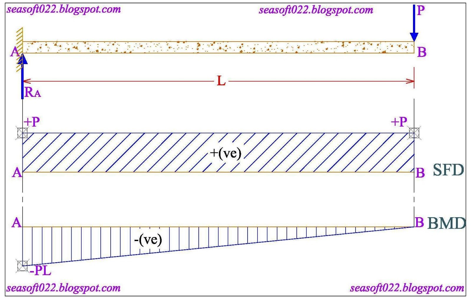
c) Let AB is a Beam of Length L, Point A is the Fixed Support, a point load P acts at the point B, then,
 |
| c) AB is a Beam of Length L, Point A is the Fixed Support, a point load P acts at the point B |
d) Let AB is a Beam of Length L, Point A is Pin Support & Point B is Roller Support, UDL Load W acts over the total length of the beam, then,
 |
| d) AB is a Beam of Length L, Point A is Pin Support & Point B is Roller Support, UDL Load W acts over the total length of the beam |
e) Let AB is a Beam of Length L, Point A and B both are Fixed Support, UDL Load W acts over the total length of the beam, then,
 |
| e) AB is a Beam of Length L, Point A and B both are Fixed Support, UDL Load W acts over the total length of the beam |
f) Let AB is a Beam of Length L, Point A is the Fixed Support, UDL Load W acts over the total length of the beam, then,
 |
| f) AB is a Beam of Length L, Point A is the Fixed Support, UDL Load W acts over the total length of the beam |
These above formulas are the necessary formulas for SFD & BMD which makes the calculation more easiest.
Now, we will go for example using these above formulas,
Example-01:
AB is a Beam of 10 feet Length, Point A is Pin Support & Point B is Roller Support, a point load of 5 kip acts at the middle portion of the beam, then,
 |
| Example-01: (Page-01 of 02) |
 |
| Example-01: (Page-02 of 02) |
Example-02:
AB is a Beam of 10 feet Length, Point A and B both are Fixed Support, a point load of 5 kip acts at the middle portion of the beam, then,
 |
| Example-02: (Page-01 of 02) |
 |
| Example-02: (Page-02 of 02) |
Example-03:
AB is a Beam of 10 feet Length, Point A is the Fixed Support, a point load of 5 kip acts at the point B, then,
 |
| Example-03: (Page-01 of 02) |
 |
| Example-03: (Page-02 of 02) |
Example-04:
AB is a Beam of 20 feet Length, Point A is Pin Support & Point B is Roller Support, UDL Load 2 kip/feet acts over the total length of the beam, then,
 |
| Example-04: (Page-01 of 02) |
 |
| Example-04: (Page-02 of 02) |
Example-05:
AB is a Beam of 20 feet Length, Point A and B both are Fixed Support, UDL Load 2 kip/feet acts over the total length of the beam, then,
 |
| Example-05: (Page-01 of 02) |
 |
| Example-05: (Page-02 of 02) |
Example-06:
AB is a Beam of 20 feet Length, Point A is the Fixed Support, UDL Load 2 kip/feet acts over the total length of the beam, then,
 |
| Example-06: (Page-01 of 02) |
 |
| Example-06: (Page-02 of 02) |
In this article, I have explained about the basic rules of SFD & BMD, How to draw SFD and BMD easily by the help of the necessary formulas. At my next upcoming article I will explain more large/difficult/critical examples.


No comments:
Post a Comment