Some days ago I have presented to you an article about "Influence Line", I hope all of you can remembered that,
http://seasoft022.blogspot.com/2013/05/influence-line.html
According to that article I am going to present to you another article about Influence Line, which is Influence Line (02). In this article I will tell you more information/rules about Influence Line with example.
So, viewers, Lets Start,
At first,
Necessary Information about Influence Line:
01. Influence Line will always in Straight Line, not in Curved Line.
02. Influence Line will not change its own slope over the related section.
03. Shear at a point: Shear at a point means to cut at that point.
Shear Positive when,
∑Fy=(summation of vertical forces) = Upward at Left section,
∑Fy=(summation of vertical forces) = Downward at Right section, and
Shear Negative when,
∑Fy=(summation of vertical forces) = Downward at Left section,
∑Fy=(summation of vertical forces) = Upward at Right section
In case of Shear Calculation,
when 1 kip load (1 kip load is the standard load value for Influence Line) acts at the left side of Shear Point then we will calculate the reaction values at right side of Shear Point and,
when 1 kip load (1 kip load is the standard load value for Influence Line) acts at the right side of Shear Point then we will calculate the reaction values at left side of Shear Point.
Now Lets See an example to understand the term "Shear" very clearly,
Assume, AB is a beam of 10 feet, now we will apply Shear at point C (middle point of AB, so AC=BC=5 feet),
Now at first when 1 kip vertically downward load acts at Left Side which moves from A to CL (CL=Just immediate Left of C), then Shear at C will be,
VC=Shear at Point C= (- RB), because Shear will be Negative (following picture-01) when
∑Fy=(summation of vertical forces) = Upward at Right side,
 |
| Picture-01: When 1 kip load acts at the left portion of Shear Point C |
Correspondingly, when 1 kip vertically downward load acts at Right Side which moves from CR to B, (CR=Just immediate Right of C), then Shear at C will be,
VC=Shear at Point C= (+ RA), because Shear will be Positive (following Picture-02) when
∑Fy=(summation of vertical forces) = Upward at Left Side,
 |
| Picture-02: When 1 kip load acts at the right portion of Shear Point C |
Analysis of a Simply Supported Beam:
Consider the Following Simply Supported Beam,
AB= 10 feet, C is the middle point of AB, So that AC=CB=5 feet,
 |
| Picture-03: AB is a Simply Supported Beam where AB= 10 feet, C is the middle point of AB, So that AC=CB=5 feet |
Influence Line (IL) for RA:
 |
| Picture-04: Influence Line (IL) for RA for above Simply Supported Beam AB |
Influence Line (IL) for RB:
 |
| Picture-05: Influence Line (IL) for RB for above Simply Supported Beam AB |
Influence Line (IL) for VC:
 |
| Picture-06: Influence Line (IL) for VC for above Simply Supported Beam AB |
Influence Line (IL) for MC:
 |
| Picture-07: Influence Line (IL) for MC for above Simply Supported Beam AB |
For any simply supported beam or, any beam with simply supported portion, we can draw the Influence Line (IL) by the above formulas/rules.
Now we are going to draw Influence Line for a Beam with mathematically calculation,
Let's Start,
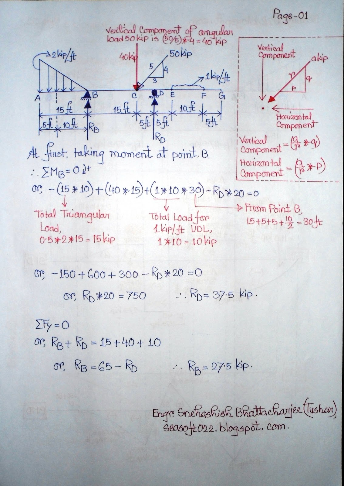
Example-01:
 |
| Picture-08: Question for Example-01 |
Solution:
When 1 kip load acts at point A, then we get,
 |
| Picture-09: When 1 kip load acts at point A |
 |
| Picture-10: When 1 kip load acts at point B |
When 1 kip load acts at point C, then we get,
 |
| Picture-11: When 1 kip load acts at point C |
When 1 kip load acts at point D, then we get,
 |
| Picture-12: When 1 kip load acts at point D |
Now, Influence Line (IL) for RA:
When 1 kip load at point A then RA= 1,
When 1 kip load at point B then RA= 0.5,
When 1 kip load at point C then RA= 0,
When 1 kip load at point D then RA= -0.6,
So, we will get Influence Line (IL) for RA which is as follows,
 |
| Picturre-13: Influence Line (IL) for RA |
Now, Influence Line (IL) for RC:
When 1 kip load at point A then RC= 0,
When 1 kip load at point B then RC= 0.5,
When 1 kip load at point C then RC= 1,
When 1 kip load at point D then RC= 1.6,
So, we will get Influence Line (IL) for RC which is as follows,
 |
| Picture-14: Influence Line (IL) for RC |
Now, we will go calculation for shear,
When 1 kip load moves from A to BL then, VB= -RC, (Right Side upward so, negative),
When 1 kip load moves from BR to D then, VB= +RA, (Left Side upward so, positive),
When 1 kip load at point B, then , VB= -RC, (when just immediate left at B) and
VB= +RA, (when just immediate right at B) both of these, at first VB= -RC, then VB= +RA, because 1 kip load moves from Left to Right,
So, value for Left Side will be the first.
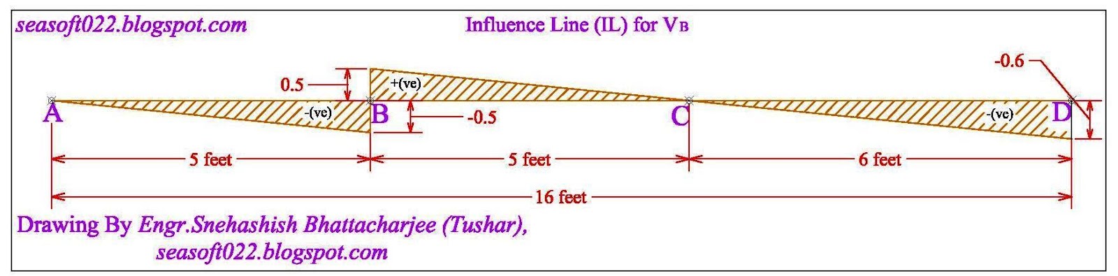
Now, Influence Line (IL) for VB:
When 1 kip load at point A then VB= -RC, So, VB=0, [when 1 kip load at point A, RC= 0]
When 1 kip load at point B (BL) then VB= -RC, So, VB=-0.5, [when 1 kip load at point B, RC=0.5]
When 1 kip load at point B (BR) then VB=+RA, So, VB=+0.5,[when 1 kip load at point B, RA=0.5]
When 1 kip load at point C then VB=+RA, So, VB=0, [when 1 kip load at point C, RA= 0]
When 1 kip load at point D then VB=+RA, So, VB=-0.6, [when 1 kip load at point D, RA=-0.6]
So, we will get Influence Line (IL) for VB which is as follows,
 |
| Picture-15: Influence Line (IL) for VB |
Now, we will go calculation for Moment,
When 1 kip load moves from A to BL then, MB=RC*5
When 1 kip load moves from BR to D then, MB=RA*5
When 1 kip load at point B, then , MB= (RC*5) or, (RA*5), in both cases the value of MB will be the same.
Now, Influence Line (IL) for MB:
When 1 kip load at point A then MB= (RC*5), So, MB=0, [when 1 kip load at point A, RC= 0]
When 1 kip load at point B then MB= (RC*5) or (RA*5) So, MB= 0.5*5=2.5, [when 1 kip load at point B, RA=RC=0.5]
When 1 kip load at point C then MB=RA*5, So, MB=0, [when 1 kip load at point C, RA= 0]
When 1 kip load at point D then MB=RA*5 So, MB=(-0.6*3), MB=3, [when 1 kip load at point D, RA=-0.6]
So, we will get Influence Line (IL) for MB which is as follows,
 |
| Picture-16: Influence Line (IL) for MB |
Now if we want to create a Data Chart by collecting these values, then we get the following chart,
 |
| Picture-17: Data Chart for Example-01 |
Dear Viewers,
May be this article as well as this example become very large, but it is not large actually, Because of the necessary explanation, the solution of this mathematical problem become very lengthy/long. But if you can understand "How to draw Influence Line (IL)" clearly then from the next time this lengthy explanation will not be needed, so we could draw Influence Line easily in future. Thank You.
Thanks and Regards,
Engr. Snehashish Bhattacharjee (Tushar),
SEA Soft and Design Consultants, seasoft022.blogspot.com


