Tuesday, September 13, 2016

Design Calculation Steps for Flat Slab

Hello Viewers,

Today I am going to discuss with you about the Design Calculation Steps for Flat Slab.

To Design FLAT SLAB, we have to follow Six (06) Steps Calculation, which are as follows,

1. Determine Slab Thickness, t
2. Determine Dead Load, Live Load & Total Factored Load (DL, LL & Total Load)
3. Check the Slab Thickness viability for both Punching Shear & Beam Shear
4. Calculation of Total Static Moment
5. Moment Calculation for Column Strip & Middle Strip
6. Reinforcement Calculation for Column Strip & Middle Strip

Let us discuss about the above Six (06) Steps described as follows,
 
Page-01

 
Page-02


Page-03


Page-04
 

Page-05

Dear Viewers, we have already discussed about the design calculation procedures/ steps for Designing a Flat Slab. Now, we have to go for an Example. For Design Of Flat Slab - Example-01, please go to my another another article, link is given below,

Design of Flat Slab - (Example-01)

Viewers,
More examples about "Design of Flat Slab" will be published soon.
Please take a look at my articles & stay tuned with SEA SOFT AND DESIGN CONSULTANTS.

Thank You for your heartiest support & cooperation.

Best Regards,
Engr. Snehashish Bhattacharjee (Tushar), MIEB
Chairman & CEO, SEA Soft and Design Consultants,
Member of The Institution of Engineers, Bangladesh
Email: sea.bd.022@gmail.com
          tushar022.ce@gmail.com

Design of Flat Slab - (Example-01)

Dear Viewers,

Hope you all are well & doing fine at your workplace.

Already I have discussed with you about the Six (06) Steps Calculation about the "DESIGN OF FLAT SLAB". Please take a look which will convenient for you to continue this example.

Here is the link below to take a look,

Design Calculation Steps for Flat Slab

Previously I noticed that, some examples on Design of Flat Slab will be published soon.

Now Welcome to my new article "Design of Flat Slab - (Example-01)".

Today, I am going to discuss with you about the Design of a Flat Slab by using Direct Design Method. I am going to describe to you a example of Flat Slab Design.

Please take a look at follows,


Page-01


Page-02


Page-03


Page-04

Page-05


Page-06


Page-07


Page-08


Page-09


Page-10


Page-11


Page-12


Page-13


So, today we have discussed an example on Design of Flat Slab by using Direct Design Method.
Hope this articles will help you.

Next, more examples about Flat Slab Design will be published soon.

Thank you for your support & cooperation.
Stay tuned with SEA SOFT AND DESIGN CONSULTANTS.

Best Regards,
Engr. Snehashish Bhattacharjee (Tushar), MIEB
Chairman & CEO, SEA Soft and Design Consultants,
Member of The Institution of Engineers, Bangladesh
Email: sea.bd.022@gmail.com
          tushar022.ce@gmail.com

Saturday, March 26, 2016

Load Bearing Capacity of a Footing

Dear Viewers,

Good Day !!! Hope you are fine & doing well at your professional life.

Today, I am going to discuss about "How to determine actual load bearing capacity & ultimate load bearing capacity of a Footing Foundation by using SPT value from Bore Hole Chart".

Lets Start,
To determine actual load bearing capacity & ultimate load bearing capacity of a Footing Foundation by using SPT value,
two types of Formula will be required,
---Meyerhoof's Formula
---Bowel's Formula

Lets see the following pictures of details calculation,


Page:01 - Formula to determine load bearing capacity of a Footing Foundation


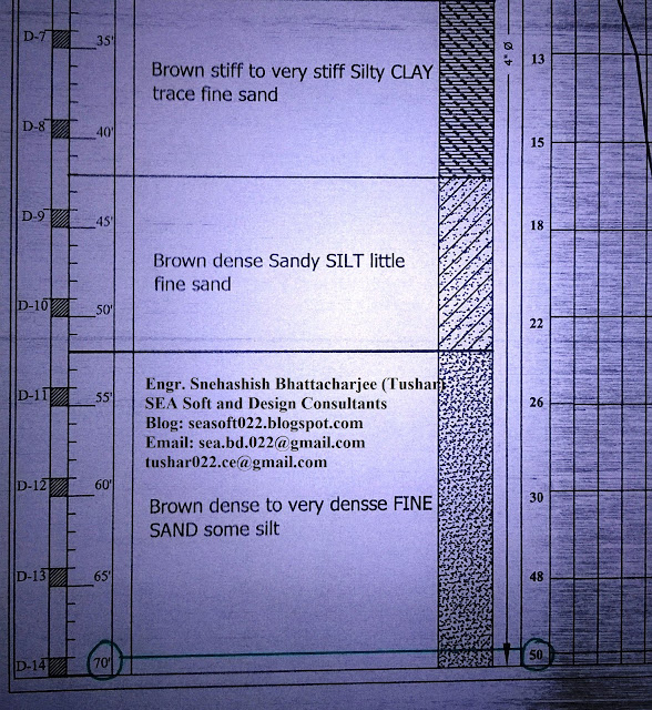
Page:02 - Bore Hole Chart (to use SPT Value)


Page:03 - Calculation details by using Meyerhoof's Formula

Page:04 - Calculation details by using Bowel's Formula


Dear Viewers,

today we have learned "How to determine actual load bearing capacity & ultimate load bearing capacity of a Footing Foundation by using SPT value from Bore Hole Chart",

My next article will be "How to determine actual load bearing capacity & ultimate load bearing capacity of a Pile Foundation by using SPT value from Bore Hole Chart",

Will be right back to you soon.
Take Care.
Good-Bye.

Have a nice day !!!

Best Regards,
Engr. Snehashish Bhattacharjee (Tushar),
SEA Soft and Design Consultants
seasoft022.blogspot.com
sea.bd.022@gmail.com
tushar022.ce@gmail.com

Friday, March 25, 2016

Load Bearing Capacity of a Cast-in-Situ Pile

Dear Viewers,

Good Day !!! Hope you are fine & doing well at your professional life.

I have already discussed to you "How to determine actual load bearing capacity & ultimate load bearing capacity of a Footing Foundation by using SPT value from Bore Hole Chart". Here is the link below, please take a look,


http://seasoft022.blogspot.com/2016/03/load-bearing-capacity-of-footing.html

Today, I am going to discuss about "How to determine actual load bearing capacity & ultimate load bearing capacity of a Pile Foundation with Pile Group by using SPT value from Bore Hole Chart".

Lets Start,
To determine actual load bearing capacity & ultimate load bearing capacity of a Pile Foundation with Pile Group by using SPT value,

Lets see the following pictures of details calculation with necessary formula,


Page:01 - Necessary Formula to determine the load bearing capacity of a Pile


Page:02 - Bore Hole Chart for using SPT Value


Page:02A - Bore Hole Chart for using SPT Value (Zoom-In)


Page:03 - Calculation data to for a Cast-in-situ Pile


Page:04 - Calculation chart to calculate Qs=qs+As


Page:05 - Load bearing capacity of a Pile Group


Page:-6 - Checking the assumed data is allowable or not


Dear Viewers,

today we have learned "How to determine actual load bearing capacity & ultimate load bearing capacity of a Pile (Cast-in-Situ) Foundation by using SPT value from Bore Hole Chart",

My next article will be "How to determine actual load bearing capacity & ultimate load bearing capacity of a Pile (Pre-Cast) Foundation by using SPT value from Bore Hole Chart",

Will be right back to you soon.
Take Care.
Good-Bye.

Have a nice day !!!

Best Regards,
Engr. Snehashish Bhattacharjee (Tushar),
SEA Soft and Design Consultants
seasoft022.blogspot.com
sea.bd.022@gmail.com
tushar022.ce@gmail.com

Friday, March 11, 2016

Response Spectrum Analysis (Dynamic Analysis) by STAAD. Pro

Response Spectrum Analysis (Dynamic Analysis) by using STAAD Pro :

Hello Viewer,
Hope you are fine & doing your best at your study & professional field.

Today I am going to describe you about the Response Spectrum Analysis (Dynamic Analysis) by using STAAD.Pro software.

Methodology: The design lateral forces at each floor in each mode is computed by STAAD in accordance with IS-1893. Please see the following pictures (my hand-notes) for details procedure.

Picture: 01


The values of (sa/g) can be calculated by Time Period (T) or, Damping Percentage (%).
At first by using, Time Period (T),
Picture: 02


Now, by using Damping Percentage (%),
Picture: 03


Picture: 04


STAAD Pro. utilizes the following steps for Dynamic Analusis or, Response Spectrum Analysis,
Picture: 05


Picture: 06


Picture: 07


Picture: 08


Picture: 09


Picture: 10


Picture: 11


Picture: 12


Picture: 13


Picture: 14


Picture: 15


Picture: 16


Picture: 17


That is all for now. Hope, you have understand about Response Spectrum Analysis (Dynamic Analysis) by using STAAD.Pro. I will again come to you for more topics related to Civil Engineering. Will get back to you soon. Take Care. Bye.

If you have any queries related any topics of Civil Engineering World, please feel free to ask me/ contact with me. Feedback/ Queries/ Questions/ Comments are always welcome.

Thanks & Best Regards,
Engr. Snehashish Bhattacharjee (Tushar),
SEA Soft and Design Consultants,
seasoft022.blogspot.com
Email: sea.bd.022@gmail.com, tushar022.ce@gmail.com